Equipment and operation: Ion implantor will be approximately 10 ft long, 10 ft wide and 10 ft high. A simplified schematic is given in Figure 7.1. We can divide the equipment into four sections as explained below.
- Ionizing chamber
- Ion selection chamber
- Acceleration chamber
- Doping chamber
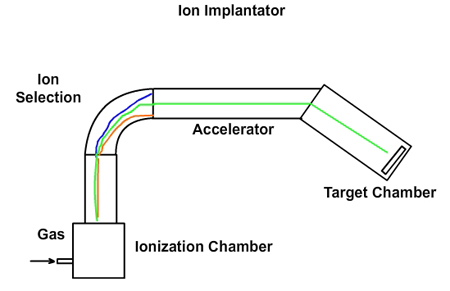
Figure 7.1. Schematic of the ion implantor
Ionizing chamber: For doping phosphorous, phosphorous pentoxide (P2O5) is used. For doping boron, boron trifluoride (BF3) is used. Phosphrous pentoxide is a solid. It has to be heated and evaporated. BF3 is a gas at normal conditions. Any material used for ion implantation must be brought to gaseous state. Let us assume that BF3 is used for doping. The atoms in BF3 must be converted to ions. In the ionizing chamber, a low pressure is maintained and a tungsten filament is heated using electricity (Figure 7.2). When it is very hot, electrons are emitted from the filament in a process called thermionic emission. Some of the electrons hit the BF3 molecules and create ions such as BF3+, BF2+, BF+ and B+. Thus ions are created from the gas.
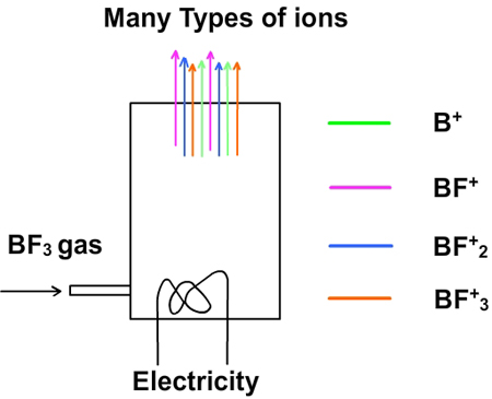
Figure 7.2 Ionizing chamber
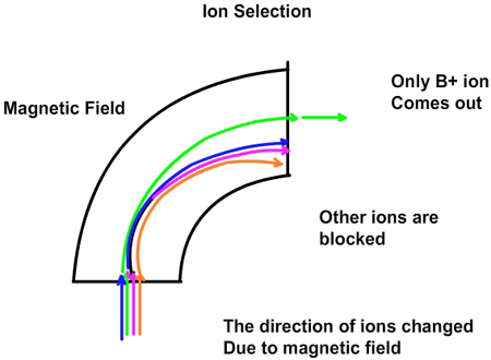
Figure 7.3. Selection chamber
|